
54 KiB
| title | author | date | isbn | publisher | category | chapter | pages |
|---|---|---|---|---|---|---|---|
| Michael Abrash's Graphics Programming Black Book, Special Edition | Michael Abrash | 1997-07-01 | 1576101746 | The Coriolis Group | Web and Software Development: Game Development,Web and Software Development: Graphics and Multimedia Development | 30 | 561-585 |
Chapter 30 -- Video Est Omnis Divisa
The Joys and Galling Problems of Using Split Screens on the EGA and VGA
The ability to split the screen into two largely independent portions one—displayed above the other on the screen—is one of the more intriguing capabilities of the VGA and EGA. The split screen feature can be used for popups (including popups that slide smoothly onto the screen), or simply to display two separate portions of display memory on a single screen. While it's possible to accomplish the same effects purely in software without using the split screen, software solutions tend to be slow and hard to implement.
By contrast, the basic operation of the split screen is fairly simple, once you grasp the various coding tricks required to pull it off, and understand the limitations and pitfalls—like the fact that the EGA's split screen implementation is a little buggy. Furthermore, panning with the split screen enabled is not as simple as it might seem. All in all, we do have some ground to cover.
Let's start with the basic operation of the split screen.
How the Split Screen Works
The operation of the split screen is simplicity itself. A split screen start scan line value is programmed into two EGA registers or three VGA registers. (More on exactly which registers in a moment.) At the beginning of each frame, the video circuitry begins to scan display memory for video data starting at the address specified by the start address registers, just as it normally would. When the video circuitry encounters the specified split screen start scan line in the course of scanning video data onto the screen, it completes that scan line normally, then resets the internal pointer which addresses the next byte of display memory to be read for video data to zero. Display memory from address zero onward is then scanned for video data in the usual way, progressing toward the high end of memory. At the end of the frame, the pointer to the next byte of display memory to scan is reloaded from the start address registers, and the whole process starts over.
The net effect: The contents of display memory starting at offset zero are displayed starting at the scan line following the specified split screen start scan line, as shown in Figure 30.1. It's important to understand that the scan line that matches the split screen scan line is not part of the split screen; the split screen starts on the following scan line. So, for example, if the split screen scan line is set to zero, the split screen actually starts at scan line 1, the second scan line from the top of the screen.
If both the start address and the split screen start scan line are set to 0, the data at offset zero in display memory is displayed as both the first scan line on the screen and the second scan line. There is no way to make the split screen cover the entire screen—it always comes up at least one scan line short.
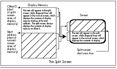
So, where is the split screen start scan line stored? The answer varies a bit, depending on whether you're talking about the EGA or the VGA. On the EGA, the split screen start scan line is a 9-bit value, with bits 7-0 stored in the Line Compare register (CRTC register 18H) and bit 8 stored in bit 4 of the Overflow register (CRTC register 7). Other bits in the Overflow register serve as the high bits of other values, such as the vertical total and the vertical blanking start. Since EGA registers are—alas!—not readable, you must know the correct settings for the other bits in the Overflow registers to use the split screen on an EGA. Fortunately, there are only two standard Overflow register settings on the EGA: 11H for 200-scan-line modes and 1FH for 350-scan-line modes.
The VGA, of course, presents no such problem in setting the split screen start scan line, for it has readable registers. However, the VGA supports a 10-bit split screen start scan line value, with bits 8-0 stored just as with the EGA, and bit 9 stored in bit 6 of the Maximum Scan Line register (CRTC register 9).
Turning the split screen on involves nothing more than setting all bits of the split screen start scan line to the scan line after which you want the split screen to start appearing. (Of course, you'll probably want to change the start address before using the split screen; otherwise, you'll just end up displaying the memory at offset zero twice: once in the normal screen and once in the split screen.) Turning off the split screen is a simple matter of setting the split screen start scan line to a value equal to or greater than the last scan line displayed; the safest such approach is to set all bits of the split screen start scan line to 1. (That is, in fact, the split screen start scan line value programmed by the BIOS during a mode set.)
The Split Screen in Action
All of these points are illustrated by Listing 30.1. Listing 30.1 fills display memory starting at offset zero (the split screen area of memory) with text identifying the split screen, fills display memory starting at offset 8000H with a graphics pattern, and sets the start address to 8000H. At this point, the normal screen is being displayed (the split screen start scan line is still set to the BIOS default setting, with all bits equal to 1, so the split screen is off), with the pixels based on the contents of display memory at offset 8000H. The contents of display memory between offset 0 and offset 7FFFH are not visible at all.
Listing 30.1 then slides the split screen up from the bottom of the screen, one scan line at a time. The split screen slides halfway up the screen, bounces down a quarter of the screen, advances another half-screen, drops another quarter-screen, and finally slides all the way up to the top. If you've never seen the split screen in action, you should run Listing 30.1; the smooth overlapping of the split screen on top of the normal display is a striking effect.
Listing 30.1 isn't done just yet, however. After a keypress, Listing 30.1 demonstrates how to turn the split screen off (by setting all bits of the split screen start scan line to 1). After another keypress, Listing 30.1 shows that the split screen can never cover the whole screen, by setting the start address to 0 and then flipping back and forth between the normal screen and the split screen with a split screen start scan line setting of zero. Both the normal screen and the split screen display the same text, but the split screen displays it one scan line lower, because the split screen doesn't start until after the first scan line, and that produces a jittering effect as the program switches the split screen on and off. (On the EGA, the split screen may display two scan lines lower, for reasons I'll discuss shortly.)
Finally, after another keypress, Listing 30.1 halts.
LISTING 30.1 L30-1.ASM
; Demonstrates the VGA/EGA split screen in action.
;
;*********************************************************************
IS_VGA               equ  1        ;set to 0 to assemble for EGA
;
VGA_SEGMENT          equ  0a000h
SCREEN_WIDTH         equ  640
SCREEN_HEIGHT        equ  350
CRTC_INDEX           equ  3d4h     ;CRT Controller Index register
OVERFLOW             equ  7        ;index of Overflow reg in CRTC
MAXIMUM_SCAN_LINEequ 9             ;index of Maximum Scan Line register
                                   ; in CRTC
START_ADDRESS_HIGH   equ  0ch      ;index of Start Address High register
                                   ; in CRTC
START_ADDRESS_LOW    equ  0dh      ;index of Start Address Low register
                                   ; in CRTC
LINE_COMPARE         equ  18h      ;index of Line Compare reg (bits 7-0
                                   ; of split screen start scan line)
                                   ; in CRTC
INPUT_STATUS_0       equ  3dah     ;Input Status 0 register
WORD_OUTS_OK         equ  1        ;set to 0 to assemble for
                                   ; computers that can't handle
                                   ; word outs to indexed VGA registers
;*********************************************************************
; Macro to output a word value to a port.
;
OUT_WORD     macro
if WORD_OUTS_OK
      out    dx,ax
else
      out    dx,al
      inc    dx
      xchg   ah,al
      out    dx,al
      dec    dx
      xchg   ah,al
endif
      endm
;*********************************************************************
MyStack      segment para stack 'STACK'
     db      512 dup (0)
MyStack      ends
;*********************************************************************
Data  segment
SplitScreenLine   dw   ?   ;line the split screen currently
                           ; starts after
StartAddress      dw   ?   ;display memory offset at which
                           ; scanning for video data starts
; Message displayed in split screen.
SplitScreenMsg    db   'Split screen text row #'
DigitInsert       dw   ?
                  db   '...$'
Data  ends
;*********************************************************************
Code  segment
      assume      cs:Code, ds:Data
;*********************************************************************
Start proc  near
      mov   ax,Data
      mov   ds,ax
;
; Select mode 10h, 640x350 16-color graphics mode.
;
      mov   ax,0010h              ;AH=0 is select mode function
                                  ;AL=10h is mode to select,
                                  ; 640x350 16-color graphics mode
      int   10h
;
; Put text into display memory starting at offset 0, with each row
; labelled as to number. This is the part of memory that will be
; displayed in the split screen portion of the display.
;
       mov   cx,25                ;# of lines of text we'll draw into
                                  ; the split screen part of memory
FillSplitScreenLoop:
       mov    ah,2                ;set cursor location function #
       sub    bh,bh               ;set cursor in page 0
       mov    dh,25
       sub    dh,cl               ;calculate row to draw in
       sub    dl,dl               ;start in column 0
       int    10h                 ;set the cursor location
       mov    al,25
       sub    al,cl               ;calculate row to draw in again
       sub    ah,ah               ;make the value a word for division
       mov    dh,10
       div    dh                  ;split the row # into two digits
       add    ax,'00'             ;convert the digits to ASCII
       mov    [DigitInsert],ax    ;put the digits into the text
                                  ; to be displayed
       mov    ah,9
       mov    dx,offset SplitScreenMsg
       int    21h                 ;print the text
       loop   FillSplitScreenLoop
;
; Fill display memory starting at 8000h with a diagonally striped
; pattern.
;
       mov    ax,VGA_SEGMENT
       mov    es,ax
       mov    di,8000h
       mov    dx,SCREEN_HEIGHT     ;fill all lines
       mov    ax,8888h             ;starting fill pattern
       cld
RowLoop:
       mov    cx,SCREEN_WIDTH/8/2  ;fill 1 scan line a word at a time
       rep    stosw                ;fill the scan line
       ror    ax,1                 ;shift pattern word
       dec    dx
       jnz    RowLoop
;
; Set the start address to 8000h and display that part of memory.
;
       mov    [StartAddress],8000h
       call   SetStartAddress
;
; Slide the split screen half way up the screen and then back down
; a quarter of the screen.
;
       mov    [SplitScreenLine],SCREEN_HEIGHT-1
                                    ;set the initial line just off
                                    ; the bottom of the screen
       mov    cx,SCREEN_HEIGHT/2
       call   SplitScreenUp
       mov    cx,SCREEN_HEIGHT/4
       call   SplitScreenDown
;
; Now move up another half a screen and then back down a quarter.
;
       mov    cx,SCREEN_HEIGHT/2
       call   SplitScreenUp
       mov    cx,SCREEN_HEIGHT/4
       call   SplitScreenDown
;
; Finally move up to the top of the screen.
;
       mov    cx,SCREEN_HEIGHT/2-2
       call   SplitScreenUp
;
; Wait for a key press (don't echo character).
;
       mov    ah,8                   ;DOS console input without echo function
       int    21h
;
; Turn the split screen off.
;
       mov    [SplitScreenLine],0ffffh
       call   SetSplitScreenScanLine
;
; Wait for a key press (don't echo character).
;
       mov    ah,8                    ;DOS console input without echo function
       int    21h
;
; Display the memory at 0 (the same memory the split screen displays).
;
       mov    [StartAddress],0
       call   SetStartAddress
;
; Flip between the split screen and the normal screen every 10th
; frame until a key is pressed.
;
FlipLoop:
       xor    [SplitScreenLine],0ffffh
       call   SetSplitScreenScanLine
       mov    cx,10
CountVerticalSyncsLoop:
       call   WaitForVerticalSyncEnd
       loop   CountVerticalSyncsLoop
       mov    ah,0bh                  ;DOS character available status
       int    21h
       and    al,al ;character available?
       jz     FlipLoop                 ;no, toggle split screen on/off status
       mov    ah,1
       int    21h                      ;clear the character
;
; Return to text mode and DOS.
;
       mov    ax,0003h                 ;AH=0 is select mode function
;AL=3 is mode to select, text mode
       int    10h                      ;return to text mode
       mov    ah,4ch
       int    21h                      ;return to DOS
Startendp
;*********************************************************************
; Waits for the leading edge of the vertical sync pulse.
;
; Input: none
;
; Output: none
;
; Registers altered: AL, DX
;
WaitForVerticalSyncStartprocnear
       mov    dx,INPUT_STATUS_0
WaitNotVerticalSync:
       in     al,dx
       test   al,08h
       jnz    WaitNotVerticalSync
WaitVerticalSync:
       in     al,dx
       test   al,08h
       jz     WaitVerticalSync
       ret
WaitForVerticalSyncStart       endp
;*********************************************************************
; Waits for the trailing edge of the vertical sync pulse.
;
; Input: none
;
; Output: none
;
; Registers altered: AL, DX
;
WaitForVerticalSyncEndprocnear
       mov    dx,INPUT_STATUS_0
WaitVerticalSync2:
       in     al,dx
       test   al,08h
       jz     WaitVerticalSync2
WaitNotVerticalSync2:
       in     al,dx
       test   al,08h
       jnz    WaitNotVerticalSync2
       ret
WaitForVerticalSyncEndendp
;*********************************************************************
; Sets the start address to the value specifed by StartAddress.
; Wait for the trailing edge of vertical sync before setting so that
; one half of the address isn't loaded before the start of the frame
; and the other half after, resulting in flicker as one frame is
; displayed with mismatched halves. The new start address won't be
; loaded until the start of the next frame; that is, one full frame
; will be displayed before the new start address takes effect.
;
; Input: none
;
; Output: none
;
; Registers altered: AX, DX
;
SetStartAddress       proc    near
       call    WaitForVerticalSyncEnd
       mov     dx,CRTC_INDEX
       mov     al,START_ADDRESS_HIGH
       mov     ah,byte ptr [StartAddress+1]
       cli                       ;make sure both registers get set at once
       OUT_WORD
       mov     al,START_ADDRESS_LOW
       mov     ah,byte ptr [StartAddress]
       OUT_WORD
       sti
       ret
SetStartAddress     endp
;*********************************************************************
; Sets the scan line the split screen starts after to the scan line
; specified by SplitScreenLine.
;
; Input: none
;
; Output: none
;
; All registers preserved
;
SetSplitScreenScanLine    proc  near
       push    ax
       push    cx
       push    dx
;
; Wait for the leading edge of the vertical sync pulse. This ensures
; that we don't get mismatched portions of the split screen setting
; while setting the two or three split screen registers (register 18h
; set but register 7 not yet set when a match occurs, for example),
; which could produce brief flickering.
;
       call WaitForVerticalSyncStart
;
; Set the split screen scan line.
;
       mov    dx,CRTC_INDEX
       mov    ah,byte ptr [SplitScreenLine]
       mov    al,LINE_COMPARE
       cli                               ;make sure all the registers get set at once
       OUT_WORD                          ;set bits 7-0 of the split screen scan line
       mov    ah,byte ptr [SplitScreenLine+1]
       and    ah,1
       mov    cl,4
       shl    ah,cl                      ;move bit 8 of the split split screen scan
                                         ; line into position for the Overflow reg
       mov    al,OVERFLOW
if IS_VGA
;
; The Split Screen, Overflow, and Line Compare registers all contain
; part of the split screen start scan line on the VGA. We'll take
; advantage of the readable registers of the VGA to leave other bits
; in the registers we access undisturbed.
;
       out    dx,al                      ;set CRTC Index reg to point to Overflow
       inc    dx                         ;point to CRTC Data reg
       in     al,dx                      ;get the current Overflow reg setting
       and    al,not 10h                 ;turn off split screen bit 8
       or     al,ah                      ;insert the new split screen bit 8
                                         ; (works in any mode)
       out    dx,al                      ;set the new split screen bit 8
       dec    dx                         ;point to CRTC Index reg
       mov    ah,byte ptr [SplitScreenLine+1]
       and    ah,2
       mov    cl,3
       ror    ah,cl                      ;move bit 9 of the split split screen scan
                                         ; line into position for the Maximum Scan
                                         ; Line register
       mov    al,MAXIMUM_SCAN_LINE
       out    dx,al                      ;set CRTC Index reg to point to Maximum
                                         ; Scan Line
       inc    dx                         ;point to CRTC Data reg
       in     al,dx                      ;get the current Maximum Scan Line setting
       and    al,not 40h                 ;turn off split screen bit 9
       or     al,ah                      ;insert the new split screen bit 9
                                         ; (works in any mode)
       out    dx,al                      ;set the new split screen bit 9
else
;
; Only the Split Screen and Overflow registers contain part of the
; Split Screen start scan line and need to be set on the EGA.
; EGA registers are not readable, so we have to set the non-split
; screen bits of the Overflow register to a preset value, in this
; case the value for 350-scan-line modes.
;
       or    ah,0fh                       ;insert the new split screen bit 8
                                          ; (only works in 350-scan-line EGA modes)
       OUT_WORD                           ;set the new split screen bit 8
endif
       sti
       pop    dx
       pop    cx
       pop    ax
       ret
SetSplitScreenScanLine endp
;*********************************************************************
; Moves the split screen up the specified number of scan lines.
;
; Input: CX = # of scan lines to move the split screen up by
;
; Output: none
;
; Registers altered: CX
;
SplitScreenUp    proc    near
SplitScreenUpLoop:
       dec    [SplitScreenLine]
       call   SetSplitScreenScanLine
       loop   SplitScreenUpLoop
       ret
SplitScreenUp    endp
;*********************************************************************
; Moves the split screen down the specified number of scan lines.
;
; Input: CX = # of scan lines to move the split screen down by
;
; Output: none
;
; Registers altered: CX
;
SplitScreenDown    proc    near
SplitScreenDownLoop:
       inc    [SplitScreenLine]
       call   SetSplitScreenScanLine
       loop   SplitScreenDownLoop
       ret
SplitScreenDown    endp
;*********************************************************************
Code    ends
        end    Start
VGA and EGA Split-Screen Operation Don't Mix
You must set the IS_VGA equate at the start of Listing 30.1
correctly for the adapter the code will run on in order for the program
to perform properly. This equate determines how the upper bits of the
split screen start scan line are set by SetSplitScreenRow. If
IS_VGA is 0 (specifying an EGA target), then bit 8 of the split
screen start scan line is set by programming the entire Overflow
register to 1FH; this is hard-wired for the 350-scan-line modes of the
EGA. If IS_VGA is 1 (specifying a VGA target), then bits 8 and 9 of
the split screen start scan line are set by reading the registers they
reside in, changing only the split-screen-related bits, and writing the
modified settings back to their respective registers.
The VGA version of Listing 30.1 won't work on an EGA, because EGA registers aren't readable. The EGA version of Listing 30.1 won't work on a VGA, both because VGA monitors require different vertical settings than EGA monitors and because the EGA version doesn't set bit 9 of the split screen start scan line. In short, there is no way that I know of to support both VGA and EGA split screens with common code; separate drivers are required. This is one of the reasons that split screens are so rarely used in PC programming.
By the way, Listing 30.1 operates in mode 10H because that's the highest-resolution mode the VGA and EGA share. That's not the only mode the split screen works in, however. In fact, it works in all modes, as we'll see later.
Setting the Split-Screen-Related Registers
Setting the split-screen-related registers is not as simple a matter as merely outputting the right values to the right registers; timing is also important. The split screen start scan line value is checked against the number of each scan line as that scan line is displayed, which means that the split screen start scan line potentially takes effect the moment it is set. In other words, if the screen is displaying scan line 15 and you set the split screen start to 16, that change will be picked up immediately and the split screen will start after the next scan line. This is markedly different from changes to the start address, which take effect only at the start of the next frame.
The instantly-effective nature of the split screen is a bit of a problem, not because the changed screen appears as soon as the new split screen start scan line is set—that seems to me to be an advantage—but because the changed screen can appear before the new split screen start scan line is set.
Remember, the split screen start scan line is spread out over two or three registers. What if the incompletely-changed value matches the current scan line after you've set one register but before you've set the rest? For one frame, you'll see the split screen in a wrong place—possibly a very wrong place—resulting in jumping and flicker.
The solution is simple: Set the split screen start scan line at a time when it can't possibly match the currently displayed scan line. The easy way to do that is to set it when there isn't any currently displayed scan line—during vertical non-display time. One safe time that's easy to find is the start of the vertical sync pulse, which is typically pretty near the middle of vertical non-display time, and that's the approach I've followed in Listing 30.1. I've also disabled interrupts during the period when the split screen registers are being set. This isn't absolutely necessary, but if it's not done, there's the possibility that an interrupt will occur between register sets and delay the later register sets until display time, again causing flicker.
One interesting effect of setting the split screen registers at the start of vertical sync is that it has the effect of synchronizing the program to the display adapter's frame rate. No matter how fast the computer running Listing 30.1 may be, the split screen will move at a maximum rate of once per frame. This is handy for regulating execution speed over a wide variety of hardware performance ranges; however, be aware that the VGA supports 70 Hz frame rates in all non-480-scan-line modes, while the VGA in 480-scan-line-modes and the EGA in all color modes support 60 Hz frame rates.
The Problem with the EGA Split Screen
I mentioned earlier that the EGA's split screen is a little buggy. How? you may well ask, particularly given that Listing 30.1 illustrates that the EGA split screen seems pretty functional.
The bug is this: The first scan line of the EGA split screen—the scan line starting at offset zero in display memory—is displayed not once but twice. In other words, the first line of split screen display memory, and only the first line, is replicated one unnecessary time, pushing all the other lines down by one.
That's not a fatal bug, of course. In fact, if the first few scan lines are identical, it's not even noticeable. The EGA's split-screen bug can produce visible distortion given certain patterns, however, so you should try to make the top few lines identical (if possible) when designing split-screen images that might be displayed on EGAs, and you should in any case check how your split-screens look on both VGAs and EGAs.
There's another respect in which the EGA is inferior to the VGA when it comes to the split screen, and that's in the area of panning when the split screen is on. This isn't a bug—it's just one of the many areas in which the VGA's designers learned from the shortcomings of the EGA and went the EGA one better.
Split Screen and Panning
Back in Chapter 23, I presented a program that performed smooth horizontal panning. Smooth horizontal panning consists of two parts: byte-by-byte (8-pixel) panning by changing the start address and pixel-by-pixel intrabyte panning by setting the Pel Panning register (AC register 13H) to adjust alignment by 0 to 7 pixels. (IBM prefers its own jargon and uses the word "pel" instead of "pixel" in much of their documentation, hence "pel panning." Then there's DASD, a.k.a. Direct Access Storage Device—IBM-speak for hard disk.)
Horizontal smooth panning works just fine, although I've always harbored some doubts that any one horizontal-smooth-panning approach works properly on all display board clones. (More on this later.) There's a catch when using horizontal smooth panning with the split screen up, though, and it's a serious catch: You can't byte-pan the split screen (which always starts at offset zero, no matter what the setting of the start address registers)—but you can pel-pan the split screen.
Put another way, when the normal portion of the screen is horizontally smooth-panned, the split screen portion moves a pixel at a time until it's time to move to the next byte, then jumps back to the start of the current byte. As the top part of the screen moves smoothly about, the split screen will move and jump, move and jump, over and over. Believe me, it's not a pretty sight.
On the VGA, there is recourse. A VGA-only bit, bit 5 of the AC Mode Control register (AC register 10H), turns off pel panning in the split screen. In other words, when this bit is set to 1, pel panning is reset to zero before the first line of the split screen, and remains zero until the end of the frame. This doesn't allow you to pan the split screen horizontally, mind you—there's no way to do that—but it does let you pan the normal screen while the split screen stays rock-solid. This can be used to produce an attractive "streaming tape" effect in the normal screen while the split screen is used to display non-moving information.
The Split Screen and Horizontal Panning: An Example
Listing 30.2 illustrates the interaction of horizontal smooth panning with the split screen, as well as the suppression of pel panning in the split screen. Listing 30.2 creates a virtual screen 1024 pixels across by setting the Offset register (CRTC register 13H) to 64, sets the normal screen to scan video data beginning far enough up in display memory to leave room for the split screen starting at offset zero, turns on the split screen, and fills in the normal screen and split screen with distinctive patterns. Next, Listing 30.2 pans the normal screen horizontally without setting bit 5 of the AC Mode Control register to 1. As you'd expect, the split screen jerks about quite horribly. After a key press, Listing 30.2 sets bit 5 of the Mode Control register and pans the normal screen again. This time, the split screen doesn't budge an inch—if the code is running on a VGA.
By the way, if IS_VGA is set to 0 in Listing 30.2, the program will
assemble in a form that will run on the EGA and only the EGA. Pel
panning suppression in the split screen won't work in this version,
however, because the EGA lacks the capability to support that feature.
When the EGA version runs, the split screen simply jerks back and forth
during both panning sessions.
LISTING 30.2 L30-2.ASM
; Demonstrates the interaction of the split screen and
; horizontal pel panning. On a VGA, first pans right in the top
; half while the split screen jerks around, because split screen
; pel panning suppression is disabled, then enables split screen
; pel panning suppression and pans right in the top half while the
; split screen remains stable. On an EGA, the split screen jerks
; around in both cases, because the EGA doesn't support split
; screen pel panning suppression.
;
; The jerking in the split screen occurs because the split screen
; is being pel panned (panned by single pixels--intrabyte panning),
; but is not and cannot be byte panned (panned by single bytes--
; "extrabyte" panning) because the start address of the split screen
; is forever fixed at 0.
;*********************************************************************
IS_VGA                  equ    1            ;set to 0 to assemble for EGA
;
VGA_SEGMENT             equ    0a000h
LOGICAL_SCREEN_WIDTH    equ    1024         ;# of pixels across virtual
                                            ; screen that we'll pan across
SCREEN_HEIGHT           equ    350
SPLIT_SCREEN_START      equ    200          ;start scan line for split screen
SPLIT_SCREEN_HEIGHT     equ    SCREEN_HEIGHT-SPLIT_SCREEN_START-1
CRTC_INDEX              equ    3d4h         ;CRT Controller Index register
AC_INDEX                equ    3c0h         ;Attribute Controller Index reg
OVERFLOW                equ    7            ;index of Overflow reg in CRTC
MAXIMUM_SCAN_LINE       equ    9            ;index of Maximum Scan Line register
                                            ; in CRTC
START_ADDRESS_HIGH      equ    0ch          ;index of Start Address High register
                                            ; in CRTC
START_ADDRESS_LOW       equ    0dh          ;index of Start Address Low register
                                            ; in CRTC
HOFFSET                 equ    13h          ;index of Horizontal Offset register
                                            ; in CRTC
LINE_COMPARE            equ    18h          ;index of Line Compare reg (bits 7-0
                                            ; of split screen start scan line)
                                            ; in CRTC
AC_MODE_CONTROL         equ    10h          ;index of Mode Control reg in AC
PEL_PANNING             equ    13h          ;index of Pel Panning reg in AC
INPUT_STATUS_0          equ    3dah         ;Input Status 0 register
WORD_OUTS_OK            equ    1            ;set to 0 to assemble for
                                            ; computers that can't handle
                                            ; word outs to indexed VGA registers
;*********************************************************************
; Macro to output a word value to a port.
;
OUT_WORD    macro
if WORD_OUTS_OK
       out    dx,ax
else
       out    dx,al
       inc    dx
       xchg   ah,al
       out    dx,al
       dec    dx
       xchg   ah,al
endif
       endm
;*********************************************************************
MyStack       segment para stack 'STACK'
       db     512 dup (0)
MyStack       ends
;*********************************************************************
Datasegment
SplitScreenLine       dw    ?            ;line the split screen currently
                                         ; starts after
StartAddress          dw    ?            ;display memory offset at which
                                         ; scanning for video data starts
PelPan                db    ?            ;current intrabyte horizontal pel
                                         ; panning setting
Data    ends
;*********************************************************************
Code    segment
        assume    cs:Code, ds:Data
;*********************************************************************
Startproc    near
     mov     ax,Data
     mov     ds,ax
;
; Select mode 10h, 640x350 16-color graphics mode.
;
     mov     ax,0010h                    ;AH=0 is select mode function
                                         ;AL=10h is mode to select,
                                         ; 640x350 16-color graphics mode
     int     10h
;
; Set the Offset register to make the offset from the start of one
; scan line to the start of the next the desired number of pixels.
; This gives us a virtual screen wider than the actual screen to
; pan across.
; Note that the Offset register is programmed with the logical
; screen width in words, not bytes, hence the final division by 2.
;
     mov     dx,CRTC_INDEX
     mov     ax,(LOGICAL_SCREEN_WIDTH/8/2 shl 8) or HOFFSET
     OUT_WORD
;
; Set the start address to display the memory just past the split
; screen memory.
;
     mov    [StartAddress],SPLIT_SCREEN_HEIGHT*(LOGICAL_SCREEN_WIDTH/8)
     call    SetStartAddress
;
; Set the split screen start scan line.
;
     mov    [SplitScreenLine],SPLIT_SCREEN_START
     call   SetSplitScreenScanLine
;
; Fill the split screen portion of display memory (starting at
; offset 0) with a choppy diagonal pattern sloping left.
;
     mov     ax,VGA_SEGMENT
     mov     es,ax
     sub     di,di
     mov     dx,SPLIT_SCREEN_HEIGHT
                                              ;fill all lines in the split screen
     mov     ax,0FF0h                         ;starting fill pattern
    cld
RowLoop:
     mov     cx,LOGICAL_SCREEN_WIDTH/8/4
                                              ;fill 1 scan line
ColumnLoop:
     sto     sw                               ;draw part of a diagonal line
     mov     word ptr es:[di],0               ;make vertical blank spaces so
                                              ; panning effects can be seen easily
     inc     di
     inc     di
     loop    ColumnLoop
     rol     ax,1                             ;shift pattern word
     dec     dx
     jnz     RowLoop
;
; Fill the portion of display memory that will be displayed in the
; normal screen (the non-split screen part of the display) with a
; choppy diagonal pattern sloping right.
;
     mov     di,SPLIT_SCREEN_HEIGHT*(LOGICAL_SCREEN_WIDTH/8)
     mov     dx,SCREEN_HEIGHT                 ;fill all lines
     mov     ax,0c510h                        ;starting fill pattern
     cld
RowLoop2:
     mov     cx,LOGICAL_SCREEN_WIDTH/8/4
                                              ;fill 1 scan line
ColumnLoop2:
     sto     sw                               ;draw part of a diagonal line
     mov     word ptr es:[di],0               ;make vertical blank spaces so
                                              ; panning effects can be seen easily
     inc     di
     inc     di
loopColumnLoop2
     ror     ax,1                             ;shift pattern word
     dec     dx
     jnz     RowLoop2
;
; Pel pan the non-split screen portion of the display; because
; split screen pel panning suppression is not turned on, the split
; screen jerks back and forth as the pel panning setting cycles.
;
     mov     cx,200                   ;pan 200 pixels to the left
callPanRight
;
; Wait for a key press (don't echo character).
;
     mov     ah,8                     ;DOS console input without echo function
     int     21h
;
; Return to the original screen location, with pel panning turned off.
;
     mov     [StartAddress],SPLIT_SCREEN_HEIGHT*(LOGICAL_SCREEN_WIDTH/8)
     call    SetStartAddress
     mov     [PelPan],0
     call    SetPelPan
;
; Turn on split screen pel panning suppression, so the split screen
; won't be affected by pel panning. Not done on EGA because both
; readable registers and the split screen pel panning suppression bit
; aren't supported by EGAs.
;
if IS_VGA
     mov     dx,INPUT_STATUS_0
     in      al,dx                      ;reset the AC Index/Data toggle to
                                        ; Index state
     mov     al,20h+AC_MODE_CONTROL
                                        ;bit 5 set to 1 to keep video on
     mov     dx,AC_INDEX                ;point to AC Index/Data register
     out     dx,al
     inc     dx                         ;point to AC Data reg (for reads only)
     in      al,dx                      ;get the current AC Mode Control reg
     or      al,20h                     ;enable split screen pel panning
                                        ; suppression
     dec     dx                         ;point to AC Index/Data reg (Data for
                                        ; writes only)
     out     dx,al                      ;write the new AC Mode Control setting
                                        ; with split screen pel panning
                                        ; suppression turned on
endif
;
; Pel pan the non-split screen portion of the display; because
; split screen pel panning suppression is turned on, the split
; screen will not move as the pel panning setting cycles.
;
     mov     cx,200                     ;pan 200 pixels to the left
     call    PanRight
;
; Wait for a key press (don't echo character).
;
     mov     ah,8                       ;DOS console input without echo function
     int     21h
;
; Return to text mode and DOS.
;
     mov     ax,0003h                    ;AH=0 is select mode function
                                         ;AL=3 is mode to select, text mode
     int     10h                         ;return to text mode
     mov     ah,4ch
     int     21h                         ;return to DOS
Startendp
;*********************************************************************
; Waits for the leading edge of the vertical sync pulse.
;
; Input: none
;
; Output: none
;
; Registers altered: AL, DX
;
WaitForVerticalSyncStart     proc     near
     mov     dx,INPUT_STATUS_0
WaitNotVerticalSync:
     in      al,dx
     test    al,08h
     jnz     WaitNotVerticalSync
WaitVerticalSync:
     in      al,dx
     test    al,08h
     jz      WaitVerticalSync
     ret
WaitForVerticalSyncStart     endp
;*********************************************************************
; Waits for the trailing edge of the vertical sync pulse.
;
; Input: none
;
; Output: none
;
; Registers altered: AL, DX
;
WaitForVerticalSyncEnd     proc     near
     mov     dx,INPUT_STATUS_0
WaitVerticalSync2:
     in      al,dx
     test    al,08h
     jz      WaitVerticalSync2
WaitNotVerticalSync2:
     in      al,dx
     test    al,08h
     jnz     WaitNotVerticalSync2
     ret
WaitForVerticalSyncEnd     endp
;*********************************************************************
; Sets the start address to the value specifed by StartAddress.
; Wait for the trailing edge of vertical sync before setting so that
; one half of the address isn't loaded before the start of the frame
; and the other half after, resulting in flicker as one frame is
; displayed with mismatched halves. The new start address won't be
; loaded until the start of the next frame; that is, one full frame
; will be displayed before the new start address takes effect.
;
; Input: none
;
; Output: none
;
; Registers altered: AX, DX
;
SetStartAddress     proc     near
     call     WaitForVerticalSyncEnd
     mov      dx,CRTC_INDEX
     mov      al,START_ADDRESS_HIGH
     mov      ah,byte ptr [StartAddress+1]
     cli                               ;make sure both registers get set at once
     OUT_WORD
     mov      al,START_ADDRESS_LOW
     mov      ah,byte ptr [StartAddress]
     OUT_WORD
     sti
     ret
SetStartAddress     endp
;*********************************************************************
; Sets the horizontal pel panning setting to the value specified
; by PelPan. Waits until the start of vertical sync to do so, so
; the new pel pan setting can be loaded during non-display time
; and can be ready by the start of the next frame.
;
; Input: none
;
; Output: none
;
; Registers altered: AL, DX
;
SetPelPan     proc     near
     call     WaitForVerticalSyncStart    ;also resets the AC
                                          ; Index/Data toggle
                                          ; to Index state
     mov      dx,AC_INDEX
     mov      al,PEL_PANNING+20h          ;bit 5 set to 1 to keep video on
     out      dx,al                       ;point the AC Index to Pel Pan reg
     mov      al,[PelPan]
     out      dx,al                       ;load the new Pel Pan setting
     ret
SetPelPanendp
;*********************************************************************
; Sets the scan line the split screen starts after to the scan line
; specified by SplitScreenLine.
;
; Input: none
;
; Output: none
;
; All registers preserved
;
SetSplitScreenScanLine     proc     near
     push     ax
     push     cx
     push     dx
;
; Wait for the leading edge of the vertical sync pulse. This ensures
; that we don't get mismatched portions of the split screen setting
; while setting the two or three split screen registers (register 18h
; set but register 7 not yet set when a match occurs, for example),
; which could produce brief flickering.
;
     call     WaitForVerticalSyncStart
;
; Set the split screen scan line.
;
     mov     dx,CRTC_INDEX
     mov     ah,byte ptr [SplitScreenLine]
     mov     al,LINE_COMPARE
     cli                              ;make sure all the registers get set at once
     OUT_WORD                         ;set bits 7-0 of the split screen scan line
     mov     ah,byte ptr [SplitScreenLine+1]
     and     ah,1
     mov     cl,4
     shl     ah,cl                    ;move bit 8 of the split split screen scan
; line into position for the Overflow reg
     mov     al,OVERFLOW
if IS_VGA
;
; The Split Screen, Overflow, and Line Compare registers all contain
; part of the split screen start scan line on the VGA. We'll take
; advantage of the readable registers of the VGA to leave other bits
; in the registers we access undisturbed.
;
     out     dx,al                    ;set CRTC Index reg to point to Overflow
     inc     dx                       ;point to CRTC Data reg
     in      al,dx                    ;get the current Overflow reg setting
     and     al,not 10h               ;turn off split screen bit 8
     or      al,ah                    ;insert the new split screen bit 8
                                      ; (works in any mode)
     out     dx,al                    ;set the new split screen bit 8
     dec     dx                       ;point to CRTC Index reg
     mov     ah,byte ptr [SplitScreenLine+1]
     and     ah,2
     mov     cl,3
     ror     ah,cl                    ;move bit 9 of the split split screen scan
                                      ; line into position for the Maximum Scan
                                      ; Line register
     mov     al,MAXIMUM_SCAN_LINE
     out     dx,al                    ;set CRTC Index reg to point to Maximum
                                      ; Scan Line
     inc     dx                       ;point to CRTC Data reg
     in      al,dx                    ;get the current Maximum Scan Line setting
     and     al,not 40h               ;turn off split screen bit 9
     or      al,ah                    ;insert the new split screen bit 9
                                      ; (works in any mode)
     out     dx,al                    ;set the new split screen bit 9
else
;
; Only the Split Screen and Overflow registers contain part of the
; Split Screen start scan line and need to be set on the EGA.
; EGA registers are not readable, so we have to set the non-split
; screen bits of the Overflow register to a preset value, in this
; case the value for 350-scan-line modes.
;
     or     ah,0fh                     ;insert the new split screen bit 8
                                       ; (only works in 350-scan-line EGA modes)
     OUT_WORD                          ;set the new split screen bit 8
endif
     sti
     pop     dx
     pop     cx
     pop     ax
     ret
SetSplitScreenScanLine     endp
;*********************************************************************
; Pan horizontally to the right the number of pixels specified by CX.
;
; Input: CX = # of pixels by which to pan horizontally
;
; Output: none
;
; Registers altered: AX, CX, DX
;
PanRight     proc     near
PanLoop:
     inc     [PelPan]
     and     [PelPan],07h
     jnz     DoSetStartAddress
     inc     [StartAddress]
DoSetStartAddress:
     call    SetStartAddress
     call    SetPelPan
     loop    PanLoop
     ret
PanRight     endp
;*********************************************************************
Codeends
endStart
Notes on Setting and Reading Registers
There are a few interesting points regarding setting and reading registers to be made about Listing 30.2. First, bit 5 of the AC Index register should be set to 1 whenever palette RAM is not being set (which is to say, all the time in your code, because palette RAM should normally be set via the BIOS). When bit 5 is 0, video data from display memory is no longer sent to palette RAM, and the screen becomes a solid color—not normally a desirable state of affairs.
Recall also that the AC Index and Data registers are both written to at I/O address 3C0H, with the toggle that determines which one is written to at any time switching state on every write to 3C0H; this toggle is reset to index mode by each read from the Input Status 0 register (3DAH in color modes, 3BAH in monochrome modes). The AC Index and Data registers can also be written to at 3C1H on the EGA, but not on the VGA, so steer clear of that practice.
On the VGA, reading AC registers is a bit different from writing to them. The AC Data register can be read from 3C0H, and the AC register currently addressed by the AC Index register can be read from 3C1H; reading does not affect the state of the AC index/data toggle. Listing 30.2 illustrates reading from and writing to the AC registers. Finally, setting the start address registers (CRTC registers 0CH and 0DH) has its complications. As with the split screen registers, the start address registers must be set together and without interruption at a time when there's no chance of a partial setting being used for a frame. However, it's a little more difficult to know when that might be the case with the start address registers than it was with the split screen registers, because it's not clear when the start address is used.
You see, the start address is loaded into the EGA's or VGA's internal display memory pointer once per frame. The internal pointer is then advanced, byte-by-byte and line-by-line, until the end of the frame (with a possible resetting to zero if the split screen line is reached), and is then reloaded for the next frame. That's straightforward enough; the real question is, Exactly when is the start address loaded?
In his excellent book Programmer's Guide to PC Video Systems (Microsoft Press) Richard Wilton says that the start address is loaded at the start of the vertical sync pulse. (Wilton calls it vertical retrace, which can also be taken to mean vertical non-display time, but given that he's testing the vertical sync status bit in the Input Status 0 register, I assume he means that the start address is loaded at the start of vertical sync.) Consequently, he waits until the end of the vertical sync pulse to set the start address registers, confident that the start address won't take effect until the next frame.
I'm sure Richard is right when it comes to the real McCoy IBM VGA and EGA, but I'm less confident that every clone out there loads the start address at the start of vertical sync.
The interaction of the start address registers and the Pel Panning register is worthy of note. After waiting for the end of vertical sync to set the start address in Listing 30.2, I wait for the start of the next vertical sync to set the Pel Panning register. That's because the start address doesn't take effect until the start of the next frame, but the pel panning setting takes effect at the start of the next line; if we set the pel panning at the same time we set the start address, we'd get a whole frame with the old start address and the new pel panning settings mixed together, causing the screen to jump. As with the split screen registers, it's safest to set the Pel Panning register during non-display time. For maximum reliability, we'd have interrupts off from the time we set the start address registers to the time we change the pel planning setting, to make sure an interrupt doesn't come in and cause us to miss the start of a vertical sync and thus get a mismatched pel panning/start address pair for a frame, although for modularity I haven't done this in Listing 30.2. (Also, doing so would require disabling interrupts for much too long a time.)
What if you wanted to pan faster? Well, you could of course just move two pixels at a time rather than one; I assure you no one will ever notice when you're panning at a rate of 10 or more times per second.
Split Screens in Other Modes
So far we've only discussed the split screen in mode 10H. What about other modes? Generally, the split screen works in any mode; the basic rule is that when a scan line on the screen matches the split screen scan line, the internal display memory pointer is reset to zero. I've found this to be true even in oddball modes, such as line-doubled CGA modes and the 320x200 256-color mode (which is really a 320x400 mode with each line repeated. For split-screen purposes, the VGA and EGA seem to count purely in scan lines, not in rows or doubled scan lines or the like. However, I have run into small anomalies in those modes on clones, and I haven't tested all modes (nor, lord knows, all clones!) so be careful when using the split screen in modes other than modes 0DH-12H, and test your code on a variety of hardware.
Come to think of it, I warn you about the hazards of running fancy VGA code on clones pretty often, don't I? Ah, well—just one of the hazards of the diversity and competition of the PC market! It is a fact of life, though—if you're a commercial developer and don't test your video code on at least half a dozen VGAs, you're living dangerously.
What of the split screen in text mode? It works fine; in fact, it not only resets the internal memory pointer to zero, but also resets the text scan line counter—which marks which line within the font you're on—to zero, so the split screen starts out with a full row of text. There's only one trick with text mode: When split screen pel panning suppression is on, the pel panning setting is forced to 0 for the rest of the frame. Unfortunately, 0 is not the "no-panning" setting for 9-dot-wide text; 8 is. The result is that when you turn on split screen pel panning suppression, the text in the split screen won't pan with the normal screen, as intended, but will also display the undesirable characteristic of moving one pixel to the left. Whether this causes any noticeable on-screen effects depends on the text displayed by a particular application; for example, there should be no problem if the split screen has a border of blanks on the left side.
How Safe?
So, how safe is it to use the split screen? My opinion is that it's perfectly safe, although I'd welcome input from people with extensive split screen experience—and the effects are striking enough that the split screen is well worth using in certain applications.
I'm a little more leery of horizontal smooth scrolling, with or without the split screen. Still, the Wilton book doesn't advise any particular caution, and I haven't heard any horror stories from the field lately, so the clone manufacturers must finally have gotten it right. (I vividly remember some early clones years back that didn't quite get it right.) So, on balance, I'd say to use horizontal smooth scrolling if you really need it; on the other hand, in fast animation you can often get away with byte scrolling, which is easier, faster, and safer. (I recently saw a game that scrolled as smoothly as you could ever want. It was only by stopping it with Ctrl-NumLock that I was able to be sure that it was, in fact, byte panning, not pel panning.)
In short, use the fancy stuff—but only when you have